中文 (中国)
 Tiếng Việt
 한국어
한국어
1. Comprehensive instructions for industrial application
Operating a radiation dosimeter is never as simple as tossing it under a lamp and reading a number. To harvest data that possesses genuine value for Quality Control (QC), technicians must rigorously adhere to a strict UV meter operation guide regarding both geometric positioning and optical physics.
1.1. Step 1: Preparation and sensor surface inspection
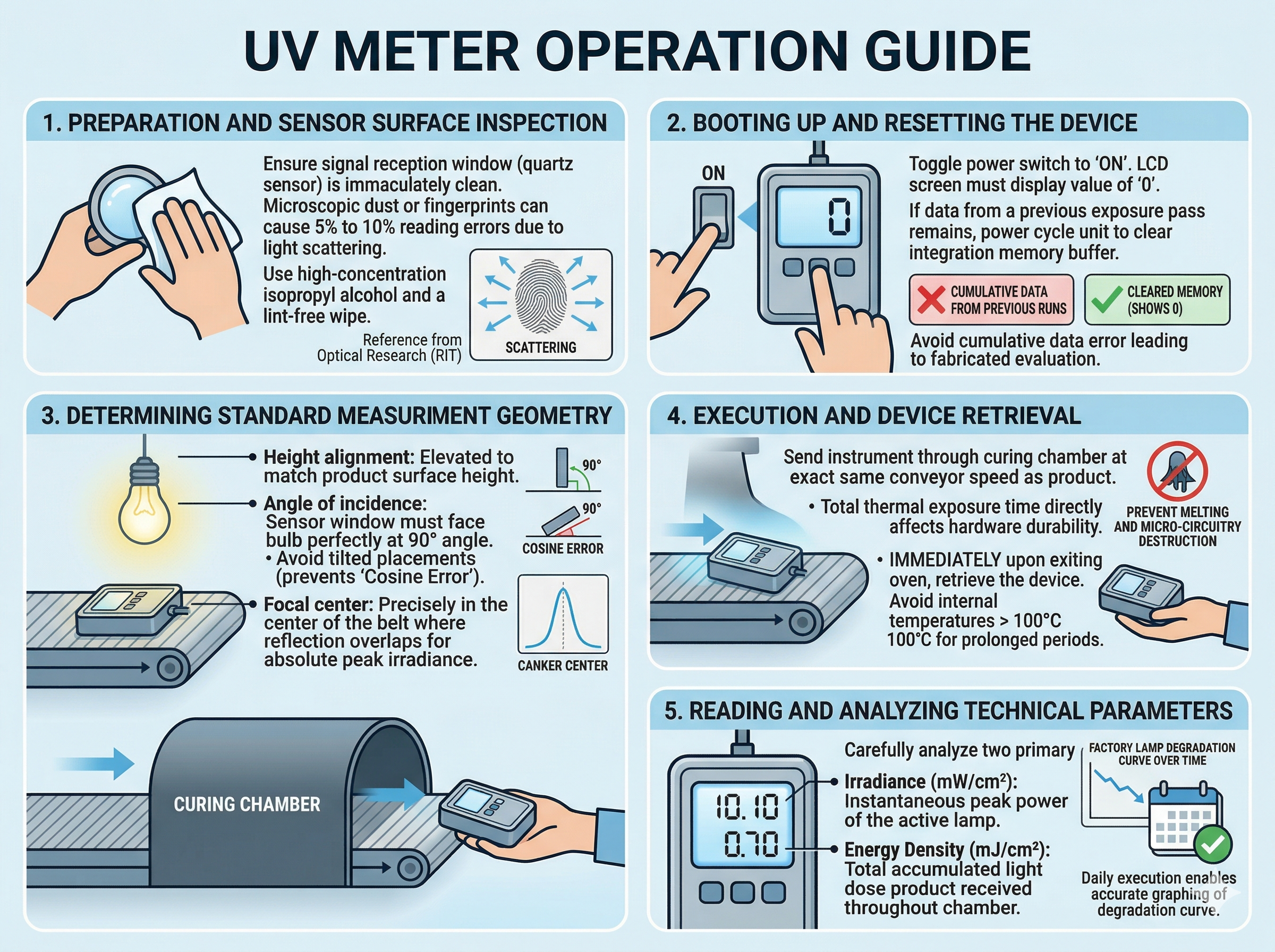
Before initiating any UV intensity measurement, ensure the signal reception window (the quartz sensor) is immaculately clean. According to optical research conducted by the Rochester Institute of Technology (RIT), even a microscopic layer of airborne dust or a faint fingerprint can induce a reading error margin of 5% to 10% due to severe light scattering. Utilizing high-concentration isopropyl alcohol and a lint-free wipe is the foundational first step in any professional UV meter operation guide.
1.2. Step 2: Booting up and resetting the device
Toggle the power switch to the “ON” position. The LCD screen must strictly display a value of “0”. If the screen retains data from a previous exposure pass, you must power cycle the unit to completely clear the integration memory buffer. A disastrously common mistake when ignoring the UV meter operation guide is recording cumulative data across multiple runs, which leads to a completely fabricated evaluation of the curing system’s actual energy output.
1.3. Step 3: Determining the standard measurement geometry
Ultraviolet radiation strictly obeys the inverse square law of physics; a minuscule change in vertical distance drastically alters the recorded intensity.
- Height alignment: The measurement device must be elevated to match the exact height of the actual product surface on the moving belt.
- Angle of incidence: The sensor window must face the bulb perfectly at a 90° angle. A reliable UV meter operation guide constantly emphasizes avoiding tilted placements, as this introduces a severe “Cosine Error” into your data set.
- Focal center: Position the unit precisely in the center of the conveyor belt where the reflection overlaps to capture the absolute peak irradiance.
1.4. Step 4: Execution and device retrieval
Send the instrument through the curing chamber at the exact same conveyor speed as your commercial product. A critical factor directly affecting hardware durability, as noted in the UV meter operation guide, is total thermal exposure time. Immediately upon exiting the oven, retrieve the device. Allowing accumulated internal temperatures to exceed 100°C for prolonged periods will catastrophically melt the optical adhesives and destroy the internal micro-circuitry.
1.5. Step 5: Reading and analyzing technical parameters
Post-exposure, you must carefully analyze two primary metrics to complete your UV intensity measurement successfully:
- Irradiance (mW/cm²): The instantaneous peak power of the active lamp.
- Energy Density (mJ/cm²): The total accumulated light dose the product received throughout the chamber.
Executing this UV meter operation guide consistently on a daily basis empowers you to accurately graph the exact degradation curve of your factory’s lamps over time.
2. Maintenance: Recognizing when to repair and replace parts
Even if you perfectly execute the daily measurement routines, all optical instruments possess a finite “photon lifespan.” After prolonged exposure to high-intensity radiation, the quartz filter undergoes a chemical and structural degradation known as “Solarization” (a deep clouding of the glass).
2.1. Warning signs requiring immediate attention
Enterprises must actively monitor their devices for the following symptoms to schedule proactive maintenance before corrupted data ruins an entire production batch:
- Erratic numerical jumping: When measuring a highly stable light source, but each pass yields numbers fluctuating by more than 15%.
- Blackened LCD corners: A clear, visual symptom of severe, cumulative thermal damage inside the curing chamber.
- Yellowed optical sensors: When the quartz window visibly loses its transparent clarity. At this stage, you must prepare to replace UV sensor components immediately to restore accuracy.
2.2. The critical role of annual calibration
A periodic 12-month UV equipment calibration is an inseparable component of compliant industrial metrology. Professors at the International RadTech Association assert that uncalibrated radiometers can drift up to 20% off-target after just one year of heavy factory use. Proper UV equipment calibration effectively resets the internal algorithmic multiplication rate, returning the device to strict NIST-traceable measurement standards.
2.3. Exactly when should you replace internal parts?
If the error margin remains unacceptably high even after a formal laboratory calibration, physical hardware intervention is required:
- Photodiodes: When intrinsic electronic sensitivity drops beyond the software’s compensation limits, you must replace UV sensor heads entirely.
- Optical Filters: When the fragile nano-coatings peel, crack, or bubble due to extreme thermal cycling.
- Lithium Batteries: When the unit repeatedly fails to boot to zero or the screen flickers randomly during operation.
Proactively addressing these physical issues saves massive repair costs and prevents sudden, catastrophic line stoppages.
3. Advanced secrets to optimize device lifespan
To drastically minimize how often you need to buy replacement parts, integrate these advanced preservation tips into your daily routine:
Practical tips for harsh environments
- Utilize thermal shields: For massive output systems (like high-power, microwave-driven mercury ovens), house the radiometer inside a specialized heat-reflecting enclosure before sending it down the line.
- Forced air cooling: Post-measurement, use a cool industrial fan to rapidly drop the internal temperature before initiating the next pass outlined in the UV meter operation guide.
- Dry storage: Ultraviolet optics are incredibly sensitive to ambient humidity. Always store the equipment in a hard protective case packed with fresh silica gel desiccants.

4. A 5-step quality control process for curing systems
For theoretical physics to generate tangible financial value, your factory’s Quality Control workflow must be highly standardized and rigorously enforced.
Standardizing your daily qc routine
- Establish a Baseline: Record reference metrics when both the bulb and aluminum reflector are 100% brand new.
- Daily Verification: Execute the UV meter operation guide precisely once at the beginning of every single production shift.
- Deviation Analysis: If the peak irradiance suddenly drops by >20%, immediately halt the line and clean the reflector housings.
- Data Logging: Maintain a strict, digitized energy diary to mathematically forecast exactly when bulbs will fail.
- Annual Servicing: Send the unit to COUSZ for deep diagnostic maintenance and certified UV equipment calibration.
5. Contact COUSZ for expert technical consultation
If you are struggling to establish a reliable measurement protocol or require rapid NIST-traceable calibration services, connect with our engineering team today. COUSZ Vietnam provides elite solutions for ultraviolet drying and advanced plasma surface treatment machinery.
For more detailed technical learning, please read our foundational articles:
- Comprehensive UV meter guide from A to Z: Easy to understand, apply right in production
- UV meter maintenance: When to perform maintenance and replace components?
5.1. Reach out to our specialists today
👤 Ms. Yuna
✨ Technical Specialist – COUSZ Vietnam
📞 Tel/Whatsapp/Wechat/Zalo: (84) 965 535 348
📧 Email: sales03@cousz.com
🌐 Website: www.cousz-vn.com
6. Faqs – frequently asked questions about device handling
6.1. Why do readings fluctuate under the same lamp?
This discrepancy is almost always caused by inconsistent geometric positioning on the belt or measuring before the lamp has achieved thermal stability. Wait at least 5-10 minutes for the bulb to warm up entirely, and guarantee the device passes exactly through the center focal point as instructed in the UV meter operation guide.
6.2. What does the “OVER” error message indicate?
This critical alert signifies that the lamp’s instantaneous power exceeds the maximum hardware threshold of the radiometer (often >5000 mW/cm²). You must either physically raise the lamp housing or procure a model with a higher dynamic measurement range. Never attempt to force a UV intensity measurement when this warning appears, as it will instantly incinerate the sensitive photodiode.
6.3. Can a mercury lamp device measure led sources?
Absolutely not. LED arrays emit incredibly narrow, spike-like spectral bands. A traditional broadband mercury meter will yield completely fabricated and potentially dangerous results if used here. You require a dedicated, narrow-band instrument specifically tuned to accurately evaluate LED systems.
6.4. How to safely clean the quartz lens without scratching?
Use a soft, lint-free optical swab lightly dampened with Isopropyl alcohol. Gently wipe in a slow, expanding spiral motion from the center outward. This specific, gentle technique is absolutely vital to protect the ultra-thin nano-coatings and significantly delay the need to replace UV sensor heads.
6.5. Does COUSZ provide on-site operational training?
Yes. We proudly provide complimentary, hands-on technical training for our clients upon equipment delivery. We ensure your QC team completely masters the entire measurement protocol, basic troubleshooting, and preventive maintenance strategies.