中文 (中国)
 Tiếng Việt
 한국어
한국어
n the highly demanding landscape of modern industrial manufacturing, achieving absolute precision at the nanometer scale is no longer an option—it is a strict necessity. The revolutionary advent of plasma surface treatment technology has created a massive turning point, completely replacing outdated, highly toxic, and inefficient chemical solvent methods. This in-depth technical article provides a comprehensive overview of modern plasma surface modification. We will dive deeply into selection criteria, compare critical technical specifications, and provide practical, scientific evidence to help you aggressively optimize your automated production lines.
1. How to select the right plasma surface treatment system for your enterprise?
1.1. Based on geometric characteristics and material structure
To successfully implement plasma surface treatment technology on your factory floor, the absolute first step is to definitively analyze the base material type and the complex geometry of the product. An ultra-thin, flat 2D polymer film requires a completely different nozzle architecture compared to a complex 3D molded plastic block or a precision machined metal component featuring deep blind holes and narrow grooves.
Investing in a high-end plasma surface treater requires factory managers to meticulously balance capital expenditures against operational efficiency. According to an extensive technical report published in the Surface & Coatings Technology Journal (2024), selecting the incorrect nozzle profile (for instance, using a direct jet on a wide, curved surface instead of a rotary sweeping nozzle) can drastically reduce the surface activation efficiency by up to 40%. This severe drop in efficiency directly translates to weak interfacial bonding and a high risk of catastrophic delamination in the field.
| Product Name | Model / Size | Configuration | Usage Effects and Issues | Fixed Accessories |
|---|---|---|---|---|
| D01 | 2mm thick | Default | Average heat dissipation | Ceramic, Electrode, Torch head body |
| 2mm hole | Optional | Good heat dissipation, but flame is unstable | ||
| 2.5mm | Optional | Stable heat and flame | ||
| 3.5mm | Optional | Highest temperature, good heat dissipation | ||
| 4mm / 5mm | Optional | Less common, good for line-type metal treatment | ||
| Linear 14mm | Optional | Custom part; flame eruption may damage one side of the nozzle | ||
| Low-temp Jet Head Gun | 2mm | Optional | Best for non-heat-resistant plastic (e.g., Shunwei AR glasses legs) | Different electrode/nozzle/sleeve; others same as direct spray. Can use direct spray body, change electrode, keep nozzle. |
| R01 | 25mm/30mm/35mm | Optional | Stable flame efficiency with moderate temperature. | Ceramic, Electrode, Motor, Motor cable, Torch head body |
| 50mm | Default | Flame range 60-70mm, fast temp rise, good for large areas | ||
| 70mm / 90mm | Optional | Custom sleeve; nozzle is heavy, large vibration below the sleeve |
1.2. Calculating actual power output and conveyor speed
The operational speed of your automated conveyor line is a vital, life-or-death factor that dictates the required configuration of your plasma surface treatment machine. If you select an RF generator with an inherently low power output and deploy it on a high-speed conveyor belt, the substrate will suffer from insufficient exposure time (dwell time). This lack of kinetic energy prevents the plasma from effectively breaking carbon bonds, resulting in highly erratic, “patchy” surface activation and ultimately, failed adhesion.
Conversely, if an engineer calibrates the system with excessive, redundant power, the resulting thermal buildup can easily warp, scorch, or completely melt highly heat-sensitive polymer films (a phenomenon known as thermal over-treatment). To avoid these costly extremes, manufacturing enterprises must conduct rigorous, hands-on laboratory demonstrations (lab tests) using their exact product samples to lock in the most precise and optimized processing parameters.
2. What differentiates plasma coating and surface treatment from other techniques?
2.1. Analyzing the pros and cons of traditional solutions
Historically, industrial factories relied heavily on rudimentary mechanical sanding or aggressive chemical primers to abrade the outermost layer of a material. However, in the modern manufacturing era, these legacy techniques are highly problematic. Mechanical sanding generates massive clouds of microscopic dust and dangerous static electricity, while chemical liquid primers emit highly toxic Volatile Organic Compounds (VOCs). Both methods severely violate the stringent, modern Environmental, Social, and Governance (ESG) protection standards that global enterprises must now follow.
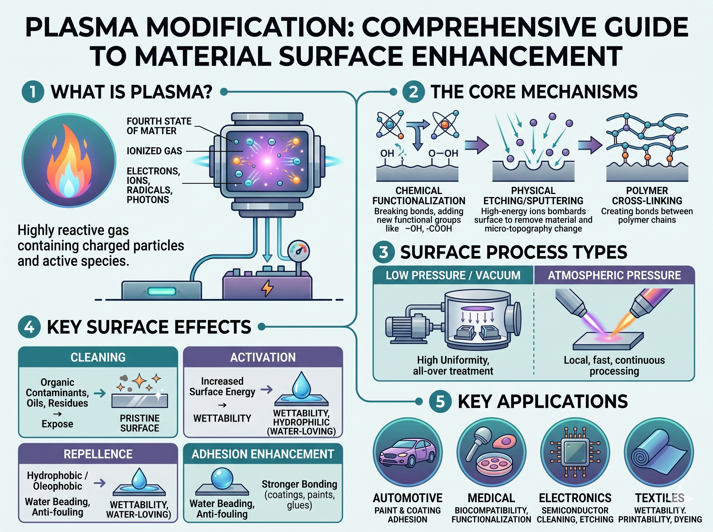
When you aggressively apply plasma surface treatment technology, the entire chemical activation process occurs via a 100% dry, eco-friendly procedure (dry process). The ionized plasma gas strictly interacts at a nanometer depth on the outermost molecular layer. It effortlessly performs deep plasma surface cleaning and functionalization without ever compromising or altering the internal mechanical bulk properties of the base material.
2.2. Superiority in startup time and factory automation
The most profound difference between an advanced ionized gas system and traditional radiation or thermal systems lies in their absolute operational speed. For a prime example, traditional industrial UV curing systems that still rely on legacy mercury bulbs mandate a standard, non-negotiable startup and warm-up time of 5 to 10 minutes just to reach their peak operational intensity. This lengthy delay causes massive bottlenecks and wastes highly valuable production time.
In brilliant contrast, a modern plasma surface treater featuring a solid-state RF generator can be toggled on and off, instantly reaching 100% maximum output power in a fraction of a second. This instantaneous response capability allows these systems to be effortlessly programmed and deeply integrated into multi-axis robotic arms. They can operate smoothly 24/7, perfectly matching the high-speed takt time of an automated factory without ever causing a single second of operational interruption.
3. How do the operational mechanisms of plasma surface cleaning and corona methods differ?
3.1. The fundamental difference in electric fields and gas flow
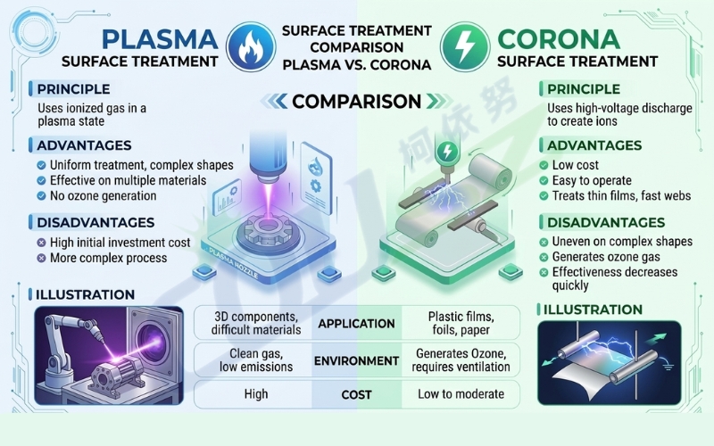
Many process engineers frequently confuse these two distinct methodologies because both rely on high-voltage electrical fields. However, traditional Corona technology utilizes ambient, free atmospheric air to violently discharge an electrical arc directly onto the material’s surface. If the substrate possesses an uneven thickness or a complex 3D shape, this crude method is highly prone to generating severe, concentrated electrical arcs that can instantly burn or “punch through” the product.
Meanwhile, plasma surface treatment technology utilizes a highly controlled, metered flow of specific process gases (such as Argon, ultra-pure N2, or Clean Dry Air – CDA filtered through heavy-duty membranes). This gas passes through a powerful, contained electromagnetic field inside the nozzle chamber before being blown outward. As a result, the emitted plasma plume carries a significantly higher energy density while remaining entirely potential-free (meaning it carries absolutely no static electrical charge).
Another massive advantage of the plasma activation process is its commitment to occupational health and safety. Unlike outdated corona discharge methods that generate dangerously high concentrations of toxic ozone gas, a well-calibrated plasma cleaner is perfectly safe for factory personnel to operate in close proximity.
3.2. Visual technical comparison and tangible business benefits
To empower your enterprise to make the most mathematically sound investment decision, please review the following technical comparison table, cross-referenced with empirical data from the Journal of Adhesion Science and Technology:
| Technical Criteria | Traditional Corona Technology | Plasma Surface Treatment Technology |
|---|---|---|
| Optimal Material Geometry | Strictly ultra-thin films, flat packaging, paper | Complex 3D plastics, heavy metals, glass, PCBs |
| Achievable Surface Energy | Moderate (typically stalling at 38-42 dynes/cm) | Extremely High (effortlessly exceeding 72 dynes/cm) |
| Static Electricity Risk | Very high, fatal risk of destroying microchips | Absolutely safe, 100% potential-free output |
| Treatment Uniformity | Prone to streaking and spotting due to arcing | 100% uniform consistency driven by pneumatic pressure |
🔥 Tangible benefits for the enterprise: By upgrading to a high-end, static-free ionized gas system, electronics manufacturing facilities not only completely eliminate the catastrophic risk of frying expensive microcircuits, but they also cut their consumption of expensive structural adhesives by up to 30%. Driving the paint peeling defect rate down to absolute zero aggressively protects your brand’s prestige and saves hundreds of thousands of dollars in warranty and recall costs.
4. What factors determine the actual performance of a plasma surface cleaning machine?
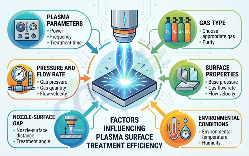
4.1. The perfect balance between gas flow rate and power
The ultimate performance and efficiency of the entire plasma surface modification process depend heavily on the precise, mathematical tuning of the central control system. If the volume of compressed air supplied to the nozzle is too massive relative to the energy generated by the RF power supply, the highly reactive free radicals will become severely diluted. This dilution drastically cripples the system’s ability to break stable carbon bonds on the substrate.
Conversely, if the plasma surface treatment machine operates with an insufficient gas flow rate, the ionized particle stream will lack the sheer kinetic momentum required to penetrate deeply into the narrow crevices and microscopic textures of injection-molded components. Senior process engineers must rely on high-precision Mass Flow Controllers (MFC) to perfectly dial in this delicate, critical thermodynamic balance.
4.2. Maintaining the standard working distance
The high-energy particle stream emitted by the nozzle is highly susceptible to a phenomenon known as “recombination” when exposed to atmospheric air for too long. Because of this, the physical standoff distance—measured from the absolute tip of the nozzle to the surface of the manipulated product—must be strictly clamped within an ideal operational window of 5mm to 15mm.
If this standoff distance becomes too large, the plasma surface treatment technology becomes entirely ineffective, as the energetic ions are electrically neutralized by the ambient air long before they can physically strike the material. Utilizing highly rigid, precision-machined mechanical fixtures and highly accurate robotic programming is an absolute prerequisite in any automated processing line.
4.3. Measurement methods and quality acceptance protocols
Prior to being processed, a virgin material surface is typically highly hydrophobic (water-repelling) due to its inherently low surface energy state. To conclusively verify the effectiveness of the treatment, Quality Assurance (QA) engineers deploy several strict, standardized measurement protocols:
- Dyne Pen Test (Surface Tension Inks): A rapid, on-the-spot evaluation of surface energy utilizing standardized chemical inks calibrated from 30 to 72 dynes/cm. This provides instant visual feedback on the factory floor.
- Water Drop Angle Test (Contact Angle Goniometer): The most scientifically rigorous method. When a material achieves a state of perfect hydrophilicity, the contact angle of a purified water droplet will instantly collapse to below 30 degrees, serving as absolute, irrefutable proof that the surface has been successfully activated.
- Cross-cut Tape Test (ASTM D3359): A highly aggressive mechanical destruction test executed after the coating or paint has fully cured to verify the sheer tensile strength of the interfacial bond.
In summary, integrating advanced plasma surface treatment technology into your facility is not merely about executing a microscopic cleaning step. It acts as the fundamental, technological backbone that aggressively elevates the structural quality of your entire product catalog. Gaining a profound, expert-level understanding of these physical characteristics and machine parameters will empower your enterprise to establish an unbreakable, sustainable competitive advantage in the fiercely contested global market.
5. Contact COUSZ Vietnam for plasma surface cleaning
To receive the official “Plasma Surface Treatment Machine User Manual” or to acquire expert, tailored advice on selecting the most optimal measurement and treatment systems for your enterprise’s unique demands, please contact us immediately:
- 👤 Ms. Yuna – Technical Specialist for plasma surface cleaning
- 🏢 Company: COUSZ Vietnam
- 📞 Tel/Whatsapp/Wechat/Zalo: (84) 965 535 348
- 📧 Email: sales03@cousz.com
- 🌐 Website: www.cousz-vn.com