中文 (中国)
 Tiếng Việt
 한국어
한국어
1. Why is the F580 considered the ultimate multi-channel solution?
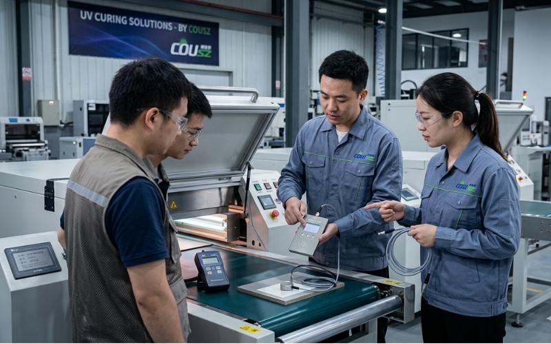
The F580 is not just a standalone testing tool; it is a highly specialized online monitoring solution that allows for simultaneous measurement across multiple physical locations (up to 8 distinct channels) within complex industrial UV LED systems. This robust instrument goes beyond basic wattage; it integrates the ability to precisely measure accumulated dose and ambient temperature, providing technicians with a comprehensive, real-time overview of the light source’s operational state.
The importance of understanding your equipment
Thoroughly mastering the F580 UV energy meter guide is incredibly crucial because each set of probes and main units is permanently linked and calibrated to a highly specific waveband (such as 365nm, 385nm, 395nm, or 405nm). According to extensive research published by the RadTech Association regarding industrial curing applications, misunderstanding the device’s spectral parameters or installing the probes incorrectly can lead to massive data deviations within the central control system, ultimately causing complete batches of printed materials or adhesives to fail.
By utilizing a true multi-channel UV radiometer, factory managers can effortlessly detect uneven light distribution across wide conveyor belts—a common phenomenon where the edges of the belt receive significantly less radiation than the center.
2. What are the detailed technical specifications of the F580?
Before diving deeply into the practical operational steps of this F580 UV energy meter guide, we must carefully review the ideal operational limits and technical parameters of the device. Exceeding these physical boundaries can irreversibly damage the delicate optical semiconductor sensors.
Physical and optical limits table
| Technical Parameter | Detailed Specification Value |
|---|---|
| Measured Spectral Range | Single-band specific (Available options: 365nm, 385nm, 395nm, 405nm) |
| Power Measurement Range | From 0 to 20,000 mW/cm² |
| Energy Measurement Range | Up to 999,999 mJ/cm² |
| Optical Accuracy | Typical error margin strictly lower than ±10% |
| Temperature Tolerance | Operates stably between -55°C and 125°C |
| Data Sampling Frequency | 10Hz (Ensuring continuous, real-time data updates for the supervisory computer) |
3. How to structure and install the device correctly?
Proper hardware installation is the foundational pillar of reliable optical metrology. This section of the F580 UV energy meter guide covers the physical interface and the strict industrial wiring requirements.
3.1. Understanding the machine structure and display
The device features a highly intuitive multi-line LCD screen alongside a straightforward navigation keypad. To successfully execute accurate UV intensity measurement protocols, you must memorize the primary functions of the three main navigational keys:
- MENU Key: Utilized to seamlessly switch between different display pages (such as moving from the main screen to the settings page) and to shift the digital cursor when adjusting numerical data values.
- MOD/- Key: Designed to move the cursor up/down or to systematically decrease parameter values during the setup phase.
- SEL/+ Key: Used to directly access specific setting menus or to sequentially increase numerical values.
3.2. Industrial wiring diagram definition
For the machine to power on and communicate without causing a catastrophic short circuit, connecting the power and signal wires must strictly adhere to the following mandated color code:
- Brown Wire: Positive DC power supply (12-24V).
- Blue Wire: Negative power supply (GND).
- Green Wire: Communication signal RS485 A+ or RS232 RXD.
- Grey Wire: Communication signal RS485 B- or RS232 TXD.
- Red & Black Wires: Output terminals for the external Alarm signal relay.
4. How to operate the device for real-world measurements?
Translating theory into factory floor practice requires discipline. This chapter of the F580 UV energy meter guide details the exact steps for daily operation.
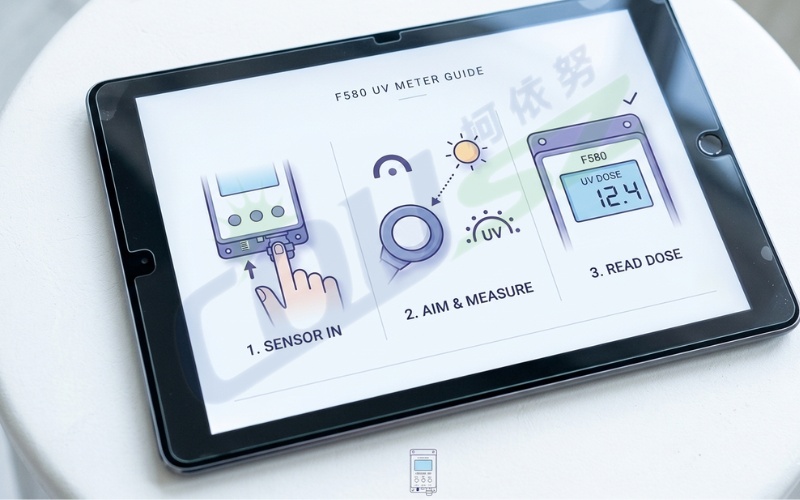
4.1. Basic measurement operations
Upon supplying power, the device briefly displays a boot screen containing its Serial Number (S/N) and network ID. Press the MENU key to transition to the main operational screen. Here, you will clearly observe the P (Power), E (Energy), and T (Temperature) parameters across all active channels, ranging from CH1 to CH8.
A critically important note in this F580 UV energy meter guide is the physical orientation of the probe. The signal reception window (the small aperture on the front face of the probe) must be directed perfectly straight and perpendicular (90 degrees) to the ultraviolet light source. Absolutely never stretch or pull the connection cables tightly, as severe mechanical tension can permanently severe the micro-wiring attached to the internal semiconductor sensor, destroying its ability to perform precise UV intensity measurement.
4.2. Setting safety alarm thresholds
To guarantee the absolute safety of your automated production line, you can proactively configure the MAXP (upper limit) and MINP (lower limit) thresholds for optical power. Whenever the actual measured power strays outside this pre-defined safety corridor, the dedicated alarm signal wire instantly outputs a voltage trigger. This automated response can activate a loud factory siren or command the central PLC to halt the conveyor belt immediately, preventing hundreds of uncured products from leaving the facility.
5. How to program the MODBUS protocol for automation?
For advanced systems integrators and automation engineers, this F580 UV energy meter guide includes essential guidelines for managing real-time data flow via the globally recognized MODBUS RTU standard.
5.1. Registers and remote control execution
Operating as a highly responsive MODBUS RTU UV meter, the F580 seamlessly integrates into large-scale Supervisory Control and Data Acquisition (SCADA) networks.
- Register Addresses: The real-time optical power data typically begins at the hexadecimal address
0x0100. - Energy Calculation: Because accumulated energy can reach massive numbers, it is stored across two 16-bit registers (High and Low). The exact mathematical formula required for your PLC logic is:
Energy = (High\ Register \times 65536) + Low\ Register - Remote Measurement Control: You can remotely trigger the energy accumulation process by writing a specific command value directly into register
0x0106. Once the designated exposure time successfully concludes, this digital switch automatically reverts to the 0 state.
Applying this section of the F580 UV energy meter guide to your PLC programming ensures that the factory’s central computer can continuously monitor the drying process 24/7, completely eliminating the need for human technicians to manually inspect the hazardous curing oven environment.
6. What are the critical maintenance and safety precautions?
No professional F580 UV energy meter guide is complete without detailing how to protect the hardware investment and maximize its operational lifespan in brutal industrial conditions.
Extending the lifespan of your sensors
- Avoid Excessive Heat: Although the probes are engineered to withstand high temperatures up to 125°C, leaving them exposed to ultra-high intensity UV radiation and scorching heat for prolonged, unnecessary durations will rapidly age the external protective casing and the internal wiring insulation.
- Probe Sanitation: Maintain the absolute cleanliness of the quartz optical window. Allowing industrial dust, chemical vapors, or sticky adhesive residue to accumulate on the lens will severely dampen the instrument’s sensitivity, causing the multi-channel UV radiometer to display artificially low readings.
- Periodic Calibration: According to NIST metrology guidelines, the manufacturer strongly recommends formally calibrating the device exactly once every year. This procedure must be performed at certified facilities equipped with standardized reference light sources to guarantee the error margin remains strictly within acceptable tolerances.
7. How to contact COUSZ for technical support?
Strictly adhering to this F580 UV energy meter guide not only aggressively protects your hardware but also guarantees that your factory’s output quality remains perfectly consistent. With its robust 8-channel capability and highly flexible communication protocols, the F580 is undeniably an indispensable tool for any industrial curing system.
If you are actively seeking the optimal solution to elevate your QC capabilities, understand the deeper role of optical metrology, or ensure your automated systems operate flawlessly, please consult our In-Depth UV Meter User Guide for Industrial Applications or contact our technical experts directly:
👤 Ms. Yuna
✨ Technical & Sales Representative – COUSZ Vietnam
📞 Tel/Whatsapp/Wechat/Zalo: (84) 965 535 348
📧 Email: sales03@cousz.com
🌐 Website: www.cousz-vn.com
8. Faqs – frequently asked questions about the F580
8.1. Can I swap the probes between different F580 main units?
No. As clearly stated in the F580 UV energy meter guide, the probes and the main processing units are explicitly calibrated together at the factory for a highly specific wavelength (e.g., 395nm). Swapping them will instantly destroy the calibration integrity and yield completely inaccurate data.
8.2. How do I connect the device to my factory’s SCADA system?
The F580 functions as a standard MODBUS RTU UV meter. You must connect the Green and Grey wires to your RS485 serial gateway and program your PLC to read the specific hex addresses (starting at 0x0100) as detailed in the communication section of this manual.
8.3. What causes the measurement readings to fluctuate wildly?
Wildly fluctuating data during UV intensity measurement usually indicates a physical problem. Check if the probe is securely mounted at a perfect 90-degree angle. Excessive vibration on the conveyor belt or a loose communication wire can also cause the 10Hz sampling rate to capture unstable, erratic data points.
8.4. Does the device need to be calibrated annually if it’s rarely used?
Yes. Optical sensors undergo natural degradation over time, even when safely stored in a toolbox. Annual calibration is a mandatory requirement under ISO 9001 quality management systems to guarantee legal compliance and measurement accuracy, regardless of the usage frequency.
8.5. How does the 8-channel system benefit wide web printing?
In wide web flexographic printing, a single lamp array might be over a meter long. A multi-channel UV radiometer like the F580 allows you to place probes at the extreme left, center, and extreme right of the web simultaneously. This instantly identifies if the edges of your lamp are degrading faster than the center, ensuring uniform curing across the entire material width.