中文 (中国)
 Tiếng Việt
 한국어
한국어
Mastering the operational process is the ultimate key to achieving absolute, flawless adhesion on any industrial surface, ranging from hydrophobic PP plastics to dense heavy metals. This comprehensive plasma cleaner user guide provided by COUSZ engineering experts will help you establish precise technical parameters (Recipes), meticulously protect your electrode systems, and aggressively maximize production efficiency right from the very first run. Let us dive deep into the standardized procedures required to fully harness the immense power of advanced surface activation technology.
1. What are the essential safety instructions for operators?
1.1. Electrical grounding and high-voltage safety precautions
To guarantee absolute safety for both the operating personnel and the sophisticated equipment, users must strictly adhere to all regulations outlined in this plasma surface treatment machine user manual. The internal architecture of this equipment generates exceptionally high voltages. Therefore, the outer chassis of the main control unit must be grounded (earthed) using proper, certified industrial techniques. Unqualified personnel or standard line workers are strictly prohibited from disassembling, modifying, or attempting to repair the control unit under any circumstances.
1.2. Nozzle connection and plasma plume restrictions
Prior to initiating the machine’s startup sequence, the operator must conduct a rigorous visual and physical inspection to ensure the plasma spray gun (nozzle) is securely connected and pointed toward a designated, safe discharge zone. Once the system is actively operating, personnel must never touch or place their hands near the ionized flame (plasma plume) emitted from the nozzle. The highly energetic particle stream can cause severe physical burns and electrical shock.
1.3. Protecting the high-voltage transmission cable
The specialized high-voltage cable that delivers energy from the generator to the spray nozzle requires meticulous protection during all daily operations. Operators must actively prevent the cable from suffering mechanical abrasions, sharp bends, prolonged exposure to extreme localized heat, or excessive tension (pulling). If any micro-fractures, cuts, or degradation are detected on the high-voltage cable jacket, the factory line must halt the use of the equipment immediately, strictly following the plasma machine operating instructions to prevent catastrophic arcing.
1.4. Mandatory protective gear and operating environment
It is strictly prohibited to touch or closely approach the high-voltage output terminal of the equipment while the machine is energized. When connecting the red high-voltage wire to the spray gun, the designated technician must wear certified, high-voltage insulated gloves and ensure the protective dielectric cap is tightly secured to guarantee absolute safety.
Furthermore, never operate this equipment in a volatile environment containing highly flammable gases, combustible vapors, or explosive airborne dust. The intense plasma beam acts as an exceptionally powerful ignition source and will trigger a catastrophic explosion under these hazardous conditions.
1.5. Managing ozone emissions in enclosed spaces
During standard operation, the ionization process of the ambient air will naturally generate a minor concentration of ozone gas (O3). While this trace amount is generally harmless and actually provides a secondary antibacterial effect, allowing ozone to accumulate in poorly ventilated areas is dangerous. If the concentration exceeds safe industrial limits, it can induce dizziness, nausea, or mild headaches in the workforce. Therefore, when following the guidelines on how to use a plasma surface cleaner in enclosed factory spaces, you must install an appropriate, high-capacity exhaust ventilation system to continuously extract the ambient air.
2. How to operate a plasma surface treatment machine safely?
2.1. Mastering the front panel interface
The front control panel is designed for rapid, intuitive adjustments on the factory floor. It houses the following critical components: the Pneumatic Pressure Gauge, the Digital Power Meter, the Pressure Adjustment Knob, the Power Adjustment Knob, the Main Power Switch, and the Operation Start Button.
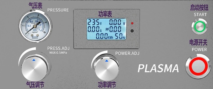
- Pneumatic Pressure Gauge: Visually displays the real-time input gas pressure, serving as your primary reference point for tuning the kinetic energy of the plasma stream.
- Operation Start Button: A tactile switch used to initiate the plasma discharge. Pressing it a second time halts the operation. Unlike traditional mercury UV curing systems that require a strict 5-10 minutes startup time, this advanced plasma equipment reaches peak operational intensity instantly.
- Power Adjustment Knob: A precision rotary dial utilized to govern the intensity of the plasma plume. Rotating the knob clockwise incrementally increases the output power.
- Digital Power Meter: A comprehensive, real-time digital display that monitors critical systemic health parameters, ensuring the operator has full visibility of the machine’s electrical state.
- Pressure Adjustment Knob: The outer ring is manipulated to throttle the input gas pressure (rotate clockwise to increase air pressure). The smaller inner knob acts as a mechanical locking mechanism to prevent accidental adjustments caused by machine vibration.
2.2. Understanding the rear panel connections
The rear panel of the control unit serves as the central hub for all physical, pneumatic, and electrical I/O connections.
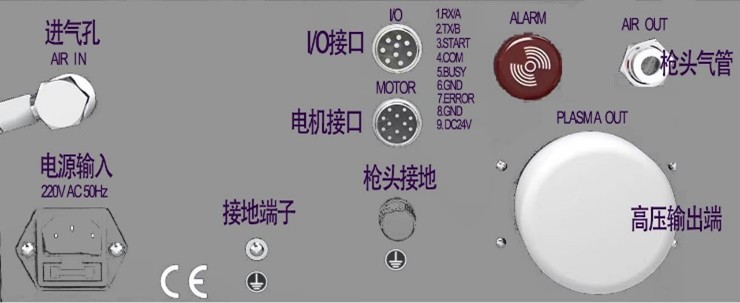
- Gas Input Port: The primary interface for your factory’s compressed air line, requiring a standard $\phi$ 6mm pneumatic tube.
- Main Grounding Terminal: Absolute proper grounding is mandatory. It is strictly recommended to utilize an industrial copper grounding wire with a cross-sectional area of 2.5mm^2 or greater.
- Nozzle Gas Output Port: Connects the gas flow from the generator to the spray gun via a fi 6mm tube.
- Nozzle Grounding Terminal: A dedicated port utilized specifically to connect the spray gun’s independent grounding wire (typically yellow-green).
- High-Voltage Output Terminal: The most critical connection point, linking to the red high-voltage cable of the spray gun. Do not touch any exposed metal during connection, wear insulated gloves, and secure the protective cover immediately.
- Motor Port (Optional): A specialized electrical connector utilized exclusively when the system is configured with a high-speed Rotary Spray Gun.
- I/O Interface: A multi-pin port designed for external PLC control and automated status monitoring (e.g., connecting to a robotic controller or a manual foot pedal).
2.3. Step-by-step connection and startup procedures
To guarantee system integrity, you must execute the physical connection sequence in this exact, non-negotiable order: Main Grounding Wire -> Spray Gun (Nozzle) -> Peripheral I/O -> Pneumatic Gas Tube -> Main Power Cord.
Step 1: Pneumatic Adjustment
The core plasma cleaning machine operating procedures mandate that the working gas pressure must be strictly maintained within the optimal range of 0.15MPa to 0.4MPa. Modifying the pressure dictates the depth of surface atomic cleaning. Please refer to our standardized laboratory recommendations below:
| Target Output Power Range | Recommended Working Air Pressure |
|---|---|
| 300W – 500W | 0.18MPa (Allowable range: 0.15 – 0.20MPa) |
| 500W – 700W | 0.23MPa (Allowable range: 0.20 – 0.25MPa) |
| 700W – 1000W | 0.25MPa (Allowable range: 0.20 – 0.30MPa) |
*Important Engineering Note: When the machine initiates the plasma arc, the dynamic pressure will naturally experience a slight drop. It is advisable to calibrate the static pressure slightly higher than the target to ensure the actual dynamic working pressure meets your process requirements.
Step 2: Calibrating the Working Distance
For maximum activation efficiency, position the substrate exactly at the center of the visible yellow/purple flame (this is the physical location where the plasma plume has the largest diameter and highest density of reactive free radicals).
Step 3: Processing Parameters
According to peer-reviewed data from leading adhesion science journals, an exposure time of merely 1 to 2 seconds is generally sufficient to completely break carbon bonds and achieve outstanding chemical activation. Absolutely never allow a stationary product to sit idly within the active plasma beam for extended periods, as this will induce severe thermal degradation, melt the polymer, or trigger a factory fire.
2.4. Maintenance guidelines and longevity tips
Following the expert recommendations in this plasma surface treatment machine operation guide, the engineering team at COUSZ dictates that the internal cooling fans, high-voltage transformers, and primary motherboard components must be thoroughly cleaned of industrial dust every 6 months to guarantee maximum heat dissipation.
- The interior of the spray gun contains fragile, high-precision ceramic components. You must strictly avoid mechanical impacts or drops during robotic installation.
- After prolonged, high-intensity industrial use, the central tungsten electrode will inevitably develop a layer of oxidation and accumulate micro-dust. This must be cleaned or replaced promptly to maintain ion density.
- When disconnecting the pneumatic tubes, you must firmly press the collet ring inward completely before pulling the tube out. Forcing the tube will instantly destroy the pneumatic fitting.
3. What are the core technical specifications and I/O definitions?
3.1. Standard electrical and environmental metrics
Understanding the fundamental capabilities of your equipment is vital for passing factory audits and ensuring long-term reliability.
- Main Power Supply: AC 220V ±10%, 50Hz. Total system power consumption is < 1500W. Standard Fuse: 10A/250V.
- Pneumatic Source Requirements: The input line pressure must be between 0.5MPa and 1MPa. The machine accepts Clean Dry Air (CDA), ultra-pure Nitrogen, or specialized precursor gases. The gas source must be 100% oil-free and moisture-free (the installation of a heavy-duty coalescing filter and water separator is mandatory).
- Safe Operating Environment: Ambient temperature from -10℃ to 40℃, with a relative factory humidity of < 80%.
3.2. Peripheral I/O interface definition for automation
To seamlessly integrate this machine into an automated robotic cell, engineers must utilize the following pinout definitions:
| Pin No. | Signal Name | Detailed Signal Content / Function |
|---|---|---|
| 1 | RX / 485A | RS232 / RS485A Receiving Port (Reserved for advanced comms) |
| 2 | TX / 485B | RS232 / RS485B Transmitting Port (Reserved for advanced comms) |
| 3 | START | External Start Control (Triggers plasma when shorted to COM) |
| 4 | COM | Common Ground point specifically for the START switch |
| 5 | BUSY | Working Status Signal (Connects to GND when machine is actively firing) |
| 6 | YV | Normally Open Solenoid Valve Control (Connects to GND) |
| 7 | ERROR | Fault Alarm Signal (Connects to GND when an error state occurs) |
| 8 | GND | DC Common Ground for the entire I/O board |
| 9 | DC24V | 24V DC Output Power Supply (Maximum load 0.5A) |
3.3. Decoding the digital power meter values
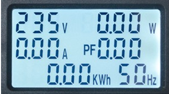
The comprehensive digital screen provides instant diagnostics. Here is the official explanation of the displayed metrics as per the plasma surface treatment equipment manual:
Display values on the plasma surface treatment machine control screen
- V (Voltage): The real-time electrical voltage supplied to the system.
- A (Amperage): The current electrical load drawn by the generator.
- W (Wattage): The active output power dictating plasma intensity.
- Hz (Hertz): The operating frequency of the electrical grid.
- PF (Power Factor): A metric of electrical efficiency; closer to 1.0 indicates optimal power utilization.
- KWh (Kilowatt-hour): The cumulative total of electrical energy consumed over the machine’s lifetime, useful for maintenance scheduling and ROI calculation.
4. How do you troubleshoot common operational faults?
4.1. Resolving sudden machine stops
If the equipment unexpectedly halts mid-operation, the root cause is typically traced to one of the following anomalies: poor physical contact at the output circuit, catastrophic high-voltage leakage, inadequate factory grounding, heavily mismatched gas pressure, a damaged nozzle load, internal overheating, or severe electrical grid interference.
Troubleshooting protocol: Immediately shut down the main power. Systematically inspect the integrity of the high-voltage cable connection. Use an electrical meter to check for voltage leakage and verify the factory ground resistance. Calibrate the input gas pressure to match the recommended table. Open the chassis to inspect the cooling fans and clear all dust. If grid interference is suspected, mandate the installation of an industrial voltage stabilizer.
4.2. Addressing low plasma power output
If the plasma plume appears weak, flickering, or visually inconsistent, it is generally caused by an unusually low factory source voltage, an abnormal electrical load within the spray gun, or highly erratic gas flow.
Troubleshooting protocol: Verify that the main AC supply is providing a stable 220V. Carefully inspect the high-voltage cable running to the spray gun for micro-fractures. Finally, disassemble the nozzle head to inspect the tungsten electrode; if it exhibits severe black oxidation, it must be thoroughly cleaned with a wire brush or replaced entirely to restore peak ionization capability.
5. Need a complete plasma surface treatment machine user manual? Contact COUSZ
Installing the hardware is merely the first physical step; truly mastering the nuanced technology is the ultimate secret to unlocking absolute interfacial adhesion. Do not allow minor operational errors to sabotage your product’s Dyne level.
We provide a comprehensive warranty covering the entire machine for 1 full year. (Electrodes and nozzles require inspection every 3 months; high-voltage cables require inspection every 3 months with a 24-month lifespan). The standard packing list includes the Main Controller, Spray Gun, Power Cord, Oil-Water Separator (Filter), IO Control Cable, Gas Tube, and a hard copy of the User Manual.
Connect with the elite engineering team at COUSZ today to receive your full, highly detailed plasma cleaner user guide. We will help your enterprise standardize operational recipes, enforce rigorous safety protocols, and train your technicians to troubleshoot faults instantly.
- ✨ Ms. Yuna – Senior Plasma & Surface Treatment Solutions Expert
- 📱 Tel/Whatsapp/Wechat/Zalo: (84) 965 535 348
- 📧 Email: sales03@cousz.com
- 🌐 Website: www.cousz-vn.com