中文 (中国)
 Tiếng Việt
 한국어
한국어
Welcome to the definitive COUSZ UV curing systems user manual. This highly detailed document is meticulously compiled to guide factory operators and process engineers on how to utilize standard spot and flood curing equipment accurately and safely. By thoroughly understanding the mechanics outlined in this guide, your facility will guarantee flawless industrial UV LED curing operation, minimize costly machine downtime, and maximize the operational lifespan of your semiconductor hardware.
Important Disclaimer: This document is an integral part of your machinery. Please store it safely for easy reference. It does not constitute a quality warranty commitment. Printing errors or technical upgrades may occur without prior notice. Strictly do not disassemble the controller or LED head casing independently; the manufacturer assumes zero liability for damages caused by unauthorized dismantling.
1. What are the safety warnings before operating the machine?
To ensure absolute stability during high-speed production and strictly protect human operators, all facility personnel must firmly adhere to the following UV curing equipment safety guidelines. Ignoring these protocols can lead to severe hardware degradation or catastrophic factory accidents.
1.1. Power supply and effective grounding protocols
Always verify that the electrical plug maintains perfect contact with the socket. The input voltage and frequency must strictly match the manufacturer’s designated parameters. The standard required input is 100–240VAC at 50–60Hz.
Furthermore, the controller chassis and the physical LED lamp head must be heavily grounded. Effective grounding completely neutralizes static electricity buildup, which is the leading cause of internal logic board failure during continuous industrial UV LED curing operation.
1.2. Thermal management and condensation prevention
Excessive thermal accumulation will cause severe hazards and permanently destroy the semiconductor diodes. You must guarantee all components receive adequate cooling:
- Air-cooled configurations: Keep the intake fans and exhaust vents completely unobstructed. Never place the controller flush against a solid wall.
- Water-cooled configurations: Ensure the circulating chiller water pipes are entirely free of kinks or blockages.
Crucial Condensation Warning: For water-cooled systems operating in high-humidity factory environments, if the chiller water temperature drops below the ambient room’s dew point, heavy condensation (water droplets) will physically form on the external pipes and directly on the sensitive LED head. If this occurs, immediately raise the chiller’s water temperature setpoint or utilize heated tracing to prevent catastrophic moisture-induced short circuits.
1.3. Uv radiation protection and emi shielding
The intense ultraviolet radiation emitted from the LED head is highly detrimental to human skin and eyes. A core pillar of our UV curing equipment safety guidelines mandates that operators must wear certified anti-UV safety goggles and protective long-sleeved clothing at all times when the machine is armed.
Additionally, beware of Electromagnetic Interference (EMI) generated by other heavy machinery on your assembly line. To prevent erratic controller behavior, always utilize high-quality shielded cables for network communication and route them completely separate from high-voltage power lines.
2. How do you navigate the main screen interface?
The primary dashboard is your command center. Referencing the COUSZ UV curing systems user manual ensures you can rapidly interpret real-time data and adjust your process on the fly.
2.1. Understanding the primary dashboard components
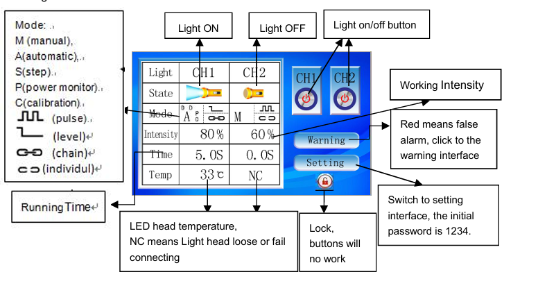
The main interface provides instant access to the operational status of the LED heads, irradiation controls, operating modes, real-time parameters, error warnings, and system locking mechanisms. Below is a breakdown of the on-screen indicators:
| Screen Indicator | Technical Meaning |
|---|---|
| CH1 / CH2 | Designates the active Channel (Lamp Head 1 or Lamp Head 2). |
| Intensity | Displays the current optical output power (Adjustable up to 100%). |
| Temp | Real-time thermal monitoring of the LED junction. |
| M (Manual Mode) | The operator manually clicks to toggle the irradiation ON or OFF. |
| A (Auto Mode) | The system automatically shuts off after a pre-programmed exposure time. |
| S (Step Mode) | Executes a continuous, multi-stage cyclic curing program (up to 8 steps). |
3. How to configure the settings interface correctly?
Accessing the settings menu allows the process engineer to fundamentally alter how the machine behaves. A proper UV LED controller interface setup is critical for seamless integration with external factory robots.
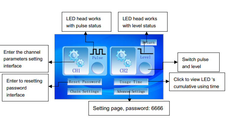
3.1. Pulse vs level mode for io control
The main settings page provides access to channel-specific parameters, startup modes, global password resets, usage time tracking, and advanced linkage setups.
When connecting the machine to an external PLC or foot pedal via the rear IO interface, you must select the correct trigger logic:
- Pulse Mode: A single momentary electrical signal (or pedal tap) toggles the machine’s state between ON and OFF.
- Level Mode: The LED head will only emit light as long as a continuous electrical high-signal is maintained. The exact moment the signal drops, the light turns OFF.
Note: When a channel is firmly locked into Level Mode during your UV LED controller interface setup, the touchscreen ON/OFF buttons are entirely disabled for that specific channel. The head can only be triggered by the external robotic IO signal.
4. How do you program the manual (m) mode?
Manual mode gives the operator absolute control over the exposure duration, making it ideal for laboratory R&D testing or highly irregular batch processing.
4.1. Configuring intensity and delay timers
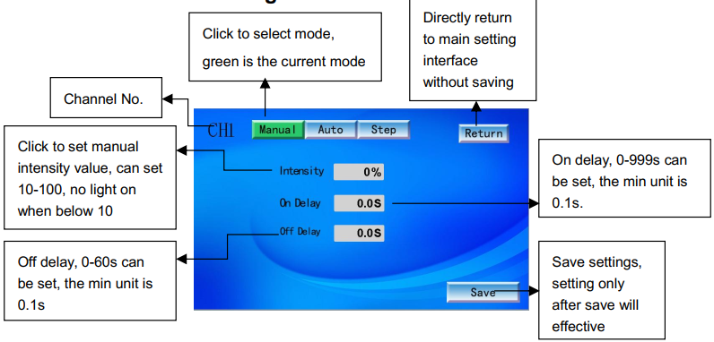
Within the Manual interface, you can adjust the following:
- Intensity: Set the desired optical strength (percentage) based on your adhesive’s requirements.
- On Delay: The programmed delay before the light activates. For example, if On Delay is set to 3 seconds, pressing “Start” will trigger a 3-second countdown before the LED physically emits light. This is useful for allowing a conveyor belt to reach its optimal speed.
- Off Delay: The programmed delay before the light deactivates after receiving a stop command.
In Manual Mode, once the light is activated, it will remain ON continuously until physically stopped. Setting an appropriate Off Delay is an excellent practice within standard UV curing equipment safety guidelines to prevent accidental prolonged exposure that could cause thermal damage to the substrate.
5. How do you optimize the automatic (a) mode?
For high-volume mass production, Automatic Mode is the industry standard. This mode guarantees that every single product receives the exact same accumulated energy dose (mJ/cm²), completely eliminating human error from the equation.
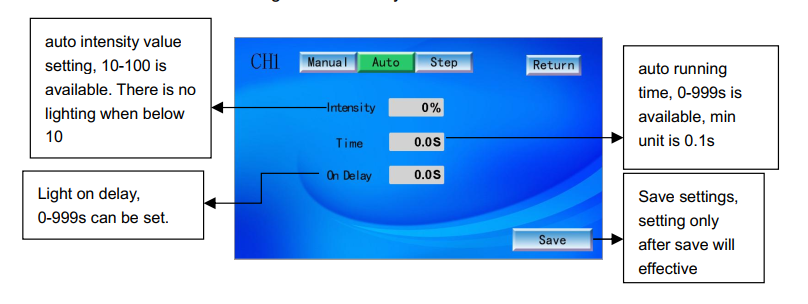
5.1. Establishing exact exposure times
In the Auto configuration page, you will set the Intensity (%), the Time (s), and the On Delay. Once the machine receives a start command, it will count down the delay, fire the LED at the precise intensity, and automatically shut down the exact millisecond the exposure time expires.
👉 Learn how to elevate your manufacturing lines:
High-speed UV Curing Technology in industrial applications
6. How to utilize the step (s) cycle mode for complex curing?
According to advanced photochemistry studies by Professor J.P. Fouassier, curing extremely thick potting resins requires a nuanced approach. Hitting thick resin with 100% power instantly can cause violent polymer shrinkage and surface wrinkling. The Step Mode resolves this by allowing you to gradually ramp up the power.
6.1. Configuring multi-stage intensities
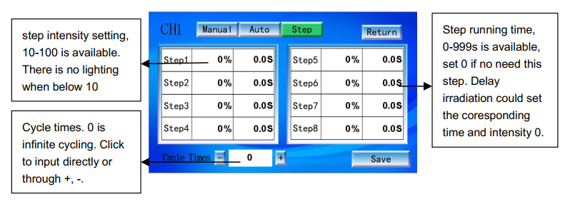
The Step interface allows the operator to freely combine different intensities and exposure times across a maximum of 8 distinct sequential steps.
- Cycle Times: Setting this to ‘0’ forces the machine to loop the 8 steps infinitely. Alternatively, you can set a hard limit between 1 and 65,535 cycles.
- Step Intensity: Adjustable from 10% to 100%. If you set a step’s intensity below 10%, the LED will not illuminate during that phase.
- Step Running Time: Adjustable from 0 to 999 seconds. If a specific step is not needed, simply set both the intensity and time to 0 to skip it.
By leveraging this feature found in the COUSZ UV curing systems user manual, engineers can create a profile that cures at 30% power for 5 seconds to gently set the surface, followed instantly by 100% power for 10 seconds to drive the photons deep into the core.
7. How do you link lamp heads and troubleshoot errors?
Industrial lines often require wide-area coverage. By properly executing your UV LED controller interface setup, you can synchronize multiple lamp heads to act as a single massive light array.
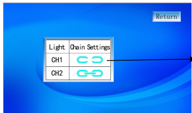
7.1. Linking channels for synchronized curing
Navigate to the linkage settings to dictate how the channels interact. The interface utilizes two distinct icons: one representing independent operation, and another representing linked operation.
When channels are linked, they fire simultaneously. Triggering an ON/OFF command for CH1 will instantly and perfectly mirror that exact command to CH2. Please note: Linking only applies to the master ON/OFF trigger. The underlying operating mode (Manual, Auto, Step) and specific intensities programmed into each individual channel remain completely unchanged.
7.2. Decoding error warnings and network communication
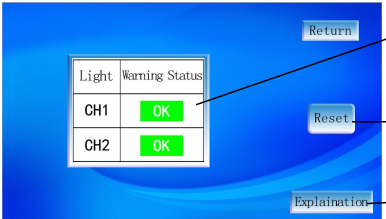
If a hardware fault occurs, the system will instantly halt the industrial UV LED curing operation and display an error code to protect the machine.
- Warning Status: Displays the current fault (e.g., Err1: LED chip failure, Err3: Over-temperature).
- Reset: Clears the fault screen after the physical issue is resolved.
- Explanation: Provides a brief on-screen diagnostic regarding the root cause.
For Industry 4.0 IoT integration, navigate to the Communication settings. Here, you can assign the machine a static IP Address, Subnet Mask, and Gateway. The Device ID parameter is crucial for uniquely identifying the machine when it is connected to a central Upper Computer (Host PLC) controlling the entire factory floor. Always press ‘Confirm’ to lock in these network changes.
8. Contact COUSZ for COUSZ UV Curing Systems User Manual
Strictly following the COUSZ UV curing systems user manual is the absolute best way to protect your capital investment and guarantee flawless manufacturing yields. However, if you encounter complex PLC integration challenges or require advanced training on chemical cross-linking parameters, our elite engineering team is ready to assist.
Contact us today for comprehensive technical support and custom automation solutions:
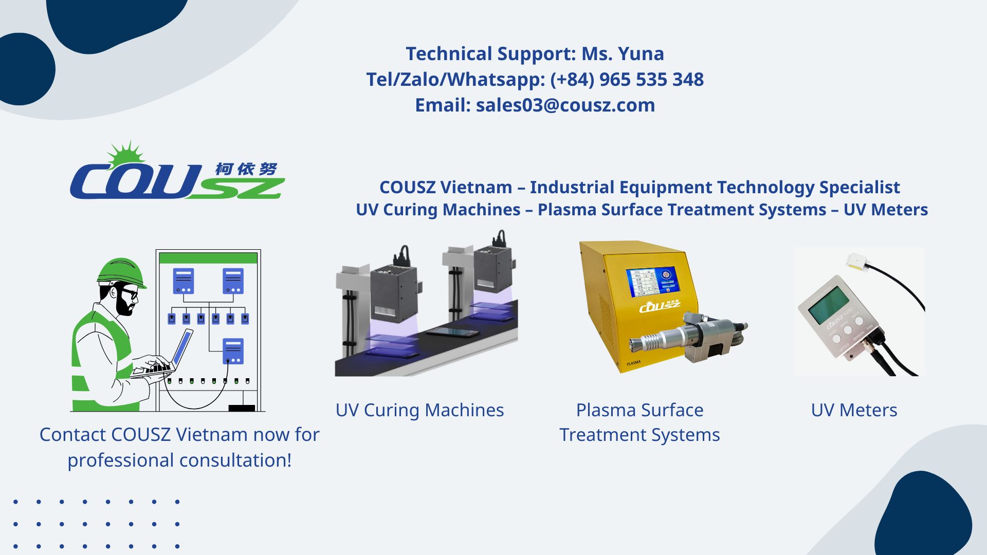
👩💼 Senior Technical Consultant: Ms. Yuna
📞 Tel / WhatsApp / WeChat / Zalo: (84) 965 535 348
📧 Email: sales03@cousz.com
🌐 Website: cousz-vn.com
📍 Headquarters: Ngo Xa Village, Phat Tich Commune, Bac Ninh Province, Vietnam.